Pre-ordersView all
-
Sideways SWCAR10C Ford Mustang GT3 Multimatic No. 65, Daytona 24H 2025 (Pre-order) $94.99

-
Sideways SWCAR09D M4 GT3 No. 46, Bathurst 12H 2024 (Pre-order) $94.99

-
Scaleauto SC-6122R Porsche 911 RSR 3.0 Jagermeister No. 54, Nurburgring 1975 $95.99

-
Slot.It CA56c Acura ARX-05 No. 7, 24h Daytona 2019 (Pre-Order) $94.99

-
Slot.It CA63b Toyota GR010 No. 7, 24h Le Mans 2025 (Pre-Order) $94.99

-
Slot.It CA60b Mazda 767B No. 203, 1st GTP 24h Le Mans 1990 (Pre-Order) $94.99

-
NSR 0649 Hypercar No. 51 (Preorder) $105.99

-
NSR 0648 Hypercar No. 50 (Preorder) $105.99
-
NSR 0626 Hypercar No. 67, Silver (Preorder) $105.99

-
NSR 0625 Hypercar No. 44, Black (Preorder) $105.99
-
Slot.It CA66a 330 P4 No. 24, Le Mans 1967 (Preorder) $0.01

-
NSR 0555SW Porsche 908/3 Tergal No. 62, Daytona '72 (PRE-ORDER) $92.99

-
NSR 0554SW Porsche 908/3 Tergal No. 40, Buenos Aires '72 (PRE-ORDER) $92.99


Recent Arrivals - CarsView all
-
Sideways SWCAR10C Ford Mustang GT3 Multimatic No. 65, Daytona 24H 2025 (Pre-order) $94.99
-
Sideways SWCAR09D M4 GT3 No. 46, Bathurst 12H 2024 (Pre-order) $94.99
-
Scaleauto SC-6365 BMW M8 GTLM R-Series, White Kit $64.99
Scaleauto SC-6365 BMW M8 GTLM R-Series, White Kit
-
RevoSlot RS0306 Ford Escort Mk1 Esso Uniflow No. 1 $99.99

-
RevoSlot RS0305 Ford Escort Mk1 No. 17, Stewart $99.99

-
RevoSlot RS0304 Datsun 510 No. 8, Azzurra $99.99

-
RevoSlot RS0303 Datsun 510 No. 95, Bob Leitzinger $99.99

-
RevoSlot RS0302 Porsche Kremer K8 White Kit, Type B Short Body $74.99

-
RevoSlot RS0301 Porsche Kremer K8 White Kit, Type A Long Body $74.99

-
RevoSlot RS0300 Porsche Kremer K8 No. 10, 24h Daytona 1995 Winner $99.99

-
RevoSlot RS0299 Porsche Kremer K8 Repsol No. 5 $99.99

-
RevoSlot RS0298 Porsche Kremer K8 Gulf No. 5 Out of stock


MR SlotcarView all
-
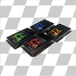
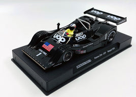
MR Slotcar MR1032 UOP Shadow DN4 No. 1, LIMITED EDITION $109.99
-
MR Slotcar MR1502 Team Cunningham C1 No. 3, 24h Le Mans Winner '60 $89.99

-
MR Slotcar MR1522 250 SWB No. 19, 1960 Le Mans $104.99

-
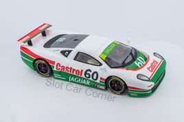
MR1086 MRSlotCar Jaguar XJ-220 Castrol No. 60, Limited Edition. $89.99
-
MR Slotcar MR1042 McLaren F1 GTR Marlboro No. 2 $89.99

-
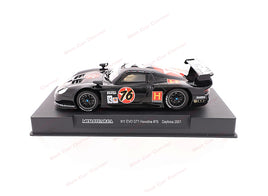
MR Slotcar MR1023 Porsche 911 GT1 EVO, Havoline No. 76 $89.99
-
MR Slotcar MR1503 C1 Corvette RAC Trophy Race 2010 No. 60 $98.39

-
MR Slotcar MR1062 333 SP MOMO No. 3, LIMITED EDITION $89.99

-
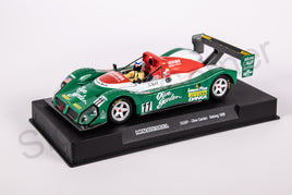
MR Slotcar MR1065 333 SP Olive Garden No. 11 $84.99


Predator MotorsView all
-
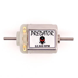
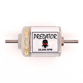
Predator SHORT-CAN 12,500 RPM FC-130 Motor, Dual Shaft $7.99
-
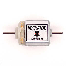
Predator SHORT-CAN 18,000 RPM FC-130 Motor, Dual Shaft $7.99
-
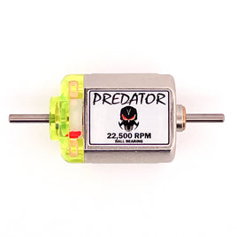
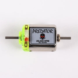
Predator 22,500 RPM Ball Bearing Motor, Dual Shaft, Short-Can $11.99
-
Predator 25,000 RPM Ball Bearing Motor, Dual Shaft, Short-Can $11.99
-
Predator SHORT-CAN 25,000 RPM FC-130 Motor, Dual Shaft Out of stock
-
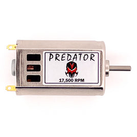
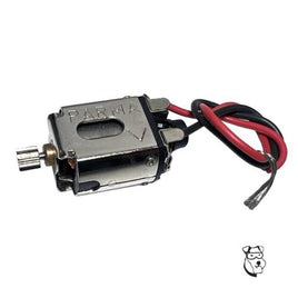
Predator LONG-CAN 17,500 RPM FK-180 Motor $8.99
-
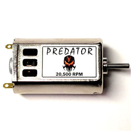
Predator LONG-CAN 20,500 RPM FK-180 Motor $8.99
-
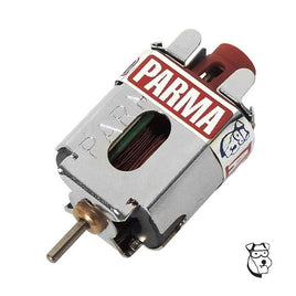
Predator LONG-CAN 22,500 RPM FK-180 Magnet Motor $12.99
-
Predator SLIM-CAN 15,000 RPM FF-050 Motor $7.99
-
Predator SLIM-CAN 18,000 RPM FF-050 Motor $7.99
-
Predator SLIM-CAN 40,000 RPM FK-050 Motor $7.99


SpecialsView all
-
RevoSlot RS0150 Toyota Supra GT Team Martini No. 15 Out of stock

-
Scalextric C4300 Chevrolet Camaro Z28 No. 77, DTM 1982 Out of stock SALE

-
Scalextric C4327 Ford Mustang GT4, Castrol Edition $47.99

$64.99SALE -
Scalextric C4351 Porsche 911 RSR 3.0 No. 60 - Le Mans 1975 Out of stock SALE

-
Scalextric C4398 Porsche 911 Carrera RSR 3.0 No. 6 Out of stock SALE

-
Scalextric C4403 Ford Mustang GT4 No. 22 $39.99

$64.99SALE -
Scalextric C4415 Porsche 911 GT3 R - British GT 2022 Out of stock SALE

-
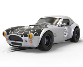
Scalextric C4417 Shelby Cobra 289 No. 94 - CSX2201 Snake Eyes Out of stock SALE
-
Scalextric C4418 Shelby Cobra 289 No. 822 - Dragon Snake - Goodwood 2021 $49.99
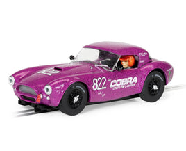
$64.99SALE -
Scalextric C4444 Mirage GR8 No. 10, 24h Le Mans 1977 $49.99

$69.99SALE -
Scalextric C4448 Ford Puma WRC No. 19 - Sebastian Loeb $52.99

$64.99SALE -
Scalextric C4449 Ford Puma WRC No. 44 - Gus Greensmith $50.99

$64.99SALE -
Scalextric C4479 Thunderbirds FAB-1 Out of stock SALE

-
Scalextric C4494 Lotus 79 No. 5, Mario Andretti $52.99

$74.99SALE -
Scalextric C4495 Ford GT40 No. 8, BOAC 500 1968 Out of stock SALE

-
Scalextric C4497 John Wick Ford - Mustang BOSS 429 Out of stock SALE


Slot.It Lightweight Sidewinder GearsView all
-
Slot.It GS17030-LPL Lightweight Plastic 17mm Sidewinder Spur Gear, 30 Tooth $8.99

-
Slot.It GS17032-LPL Lightweight Plastic 17mm Sidewinder Spur Gear, 32 Tooth $8.99

-
Slot.It GS17034-LPL Lightweight Plastic 17mm Sidewinder Spur Gear, 34 Tooth $8.99

-
Slot.It GS17531-LPL Lightweight Plastic 17.5mm Sidewinder Spur Gear, 31 Tooth $8.99

-
Slot.It GS17533-LPL Lightweight Plastic 17.5mm Sidewinder Spur Gear, 33 Tooth $8.99

-
Slot.It GS17535-LPL Lightweight Plastic 17.5mm Sidewinder Spur Gear, 35 Tooth $8.99


Color Coded Axle SpacersView all
-
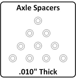
XS-01010-N SCC Axle Spacers 3/32" ID x .010" Thick, Clear $2.49
-
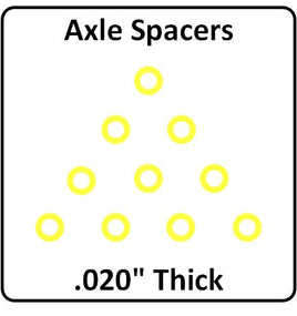
XS-02010-N SCC Axle Spacers 3/32" ID x .020" Thick, Yellow $2.49
-
XS-03010-N SCC Axle Spacers 3/32" ID x .030" Thick, Gray $2.49
-
XS-04010-N SCC Axle Spacers 3/32" ID x .040" Thick, Red $2.49
-
XS-05010-N SCC Axle Spacers 3/32" ID x .050" Thick, Purple $2.49
-
XS-06010-N SCC Axle Spacers 3/32" ID x .060" Thick, Green $2.49


ToolkitsView all
-
SCC Slot Car Maintenance Kit - 1/32 RevoSlot $26.99

-
SCC Slot Car Maintenance Kit, Deluxe Out of stock

-
SCC Slot Car Maintenance Kit, NSR Out of stock

-
SCC Slot Car Maintenance Kit, Scaleauto 1:24 $18.99

-
SCC Slot Car Maintenance Kit, Slot.it Out of stock

-
SCC Slot Car Maintenance Kit, Thunder Slot $22.99

-
Wera 671385 Tool Storage Pouch, Empty Out of stock


Styrene InteriorsView all
-
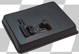
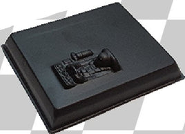
Caveman 32-0151SB Type 1 Black Styrene 1:32 Interior, Unpainted $1.29
-
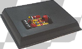
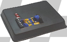
Caveman 32-0152P Type 2 Black Styrene 1:32 Interior, Painted $11.99
-
Caveman 32-0152SB Type 2 Black Styrene 1:32 Interior, Unpainted $1.09
-
Caveman 32-0151P Type 1 Black Styrene 1:32 Interior, Painted $10.99
-
Caveman 24-0037P 3D 1:24 Stock Car Interior, Painted $14.99

-
Caveman 24-0039P 3D 1:24 Late Model/Stock Car Interior, Painted $14.99